Shell and tube heat exchangers
Characteristics of shell and tube heat exchangers
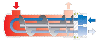
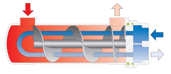
A shell-and-tube (shell-and-tube) heat exchanger is a tubular water heater of horizontal or vertical structure, which is successfully used in hot water supply systems or heating systems where piped water acts as a coolant. The principle of its operation is to heat water in the inter-tube space inside the device. The whole process is controlled by guide partitions, which are selected individually depending on the purpose of the unit.
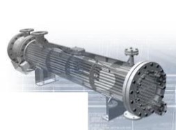
The main components of the heat exchanger shell and tube apparatus are the casing, the pipe system, the front and back wall of the water chamber. Copper, brass or corrosion-resistant steel are used for the manufacture of pipe sections. The thickness of the steel depends on the maximum pressure of the working medium and temperature. The weight of the pipe assembly is 60-80% of the total weight of the device.
Technical features of shell and tube heat exchangers for water:
- The operating temperature range of the device is from -60°C to +500°C.
- The diameter of the product ranges from 15.9 to 300 cm.
- The working pressure can reach up to 160 kgf/cm2.
- The number of tubes is from 68 to 392 pcs.
- The weight of the device can reach up to 1600 kg.
- The length of the unit ranges from several cm to 9 meters.
Pipes with an outer diameter of 25 mm with a wall thickness of 1.6-3.0 mm are most often used in that. Depending on the direction of movement of the working media, shell-and-tube heaters are divided into direct-flow, cross-flow and counter-flow types.
Design features of shell-and-tube type heat exchangers
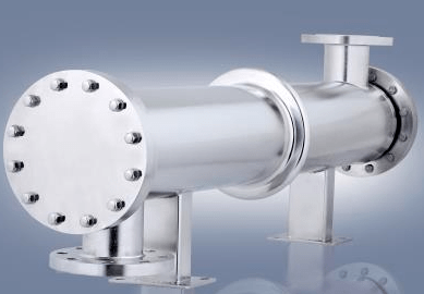
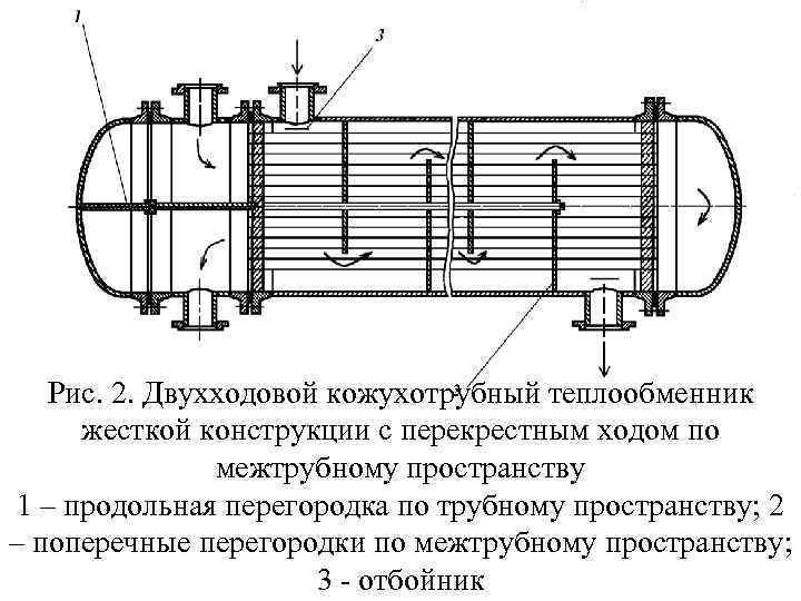
The casing, also known as the body of the heat exchanger, is made of a pipe or shell, from the end of which grilles of pipes are attached, located along the entire body. Covers are also fixed from the ends to separate the pipe and inter-pipe space. The thickness of the casing walls is calculated based on the estimated pressure of the working medium and temperature. Supports and flanges are also welded on the housing of the shell-and-tube heat exchanger.
Below is a variable circuit of a shell-and-tube heat exchanger.
We also want to present you a 3d model of a shell-and-tube heat exchanger. The video is prepared Dolotovsky Igor.
Areas of application
The shell-and-tube water-water heat exchanger is used in those production systems where heating and cooling of the liquid is required.
The purpose of the shell and tube heat exchanger can be determined by one of the letters on the label:
- T is a universal shell-and-tube device;
- K - capacitor;
- I - casing evaporator;
- X is a refrigerator.
There are the following types of heat exchangers, which are marked with a letter value:
- H - fixed tubular grilles;
- K - temperature compensator;
- N floating head;
- U-shaped pipes;
- The PC is a combined floating head and capacitor system.
The most advanced design is considered to be a floating head, which is justified by the maximum reliability in the operation of the unit. The shell-and-tube heat exchanger " tube in a pipe " is used in systems where media with increased viscosity act as a coolant. The special design ensures the normal flow of viscous media even in the presence of solid particles in them.
Calculation of the shell-and-tube heat exchanger
The thermal power of the unit is an indicator of the temperature difference, the heat transfer surface area and the heat transfer coefficient. K-heat transfer is determined by the characteristics of the flow of the medium, which are influenced by the geometry of the flow sections. In order to choose the right heat exchange equipment, it is recommended to make all the necessary calculations of the device.
The calculation of the shell-and-tube heat exchanger is carried out according to the formula:
F=Q /KΔ t cp, where
F is the heat transfer surface area;
Q is the amount of heat;
K is the heat transfer coefficient;
t - cp is the average difference of t° between the working media.
To make the calculation correctly, it is necessary to know the physical parameters of the coolant – the density and viscosity of the working medium, thermal conductivity, heat capacity at an average temperature, and the final outlet temperature.
Advantages and disadvantages of shell-and-tube devices
Advantages:
- the optimal cost
- resistance to water shocks
- low demands on the type and quality of water and coolant
- decent heating capacity
Disadvantages:
- large sizes
- weight
- Sometimes the price is too high
The company "Salutech" offers heat exchange equipment with delivery to any region of the country. If it is necessary to calculate the shell–and-tube heat exchanger, it is enough to contact the company's specialists.

